
The Elegant Mathematical Basis of Ray tracing - What Makes 3D Graphics Realistic
mathematics computer graphics
This is an essay I submitted for a collection of texts about promoting the beauty of mathematics to the masses at Monash. It goes into the mathematics of one of the most important concepts in computer graphics, but at a very fundamental level. The reader should be able to follow this text with high-school level maths.
Sypnosis
For most of my friends, the natural world, they understandably believe, is impulsive, emotional, unpredictable, overall imperfect, and should be appreciated as such but that is not the case at all. Mathematics, aside from representing how humanity sees the world, helps us human beings specify the once general, afloat phenomena and things, and through that, figuring out underlying patterns in the random and use them to our advantage. It is thanks to those exact abstract numbers and formulas that reinvented ideas once only existing in the form of imaginative thoughts, such as spellbound princesses and talking toys into colorful reality right in front of our eyes. In fact, it is thanks to mathematics that a heartwarming stories such that of a clownfish crossing the ocean to find his son could have been encapsulated in flat screens and tiny electric boxes in the first place, completely transforming and enhancing our cinematic experience. Many ingenious computational techniques are responsible for the visual masterpieces mentioned above, one of which, a method called “ray tracing”, will be investigated in detail throughout this essay.

Our light, the real kind
In order to simulate realistic lighting, we must first understand what is real light. We see the world around us by receiving light rays that bounce off of other objects to our eyes. This light is emitted by a light source, such as the sun or a lightbulb. The process seems to be rather simple so it must be easy to recreate on a computer, mustn’t it? Yes and no. It is not difficult to create a system that naively imitates the real world on a computer but it is immensely expensive to do so computationally. A real light source continuously emits an infinite amount of light rays; each of the rays bounces a number of times before it is fully absorbed or reaches our eyes - a process that requires an incredible number of computations just to mimic a single light source whereas in a typical scene of a Pixar animation, there are usually dozens.
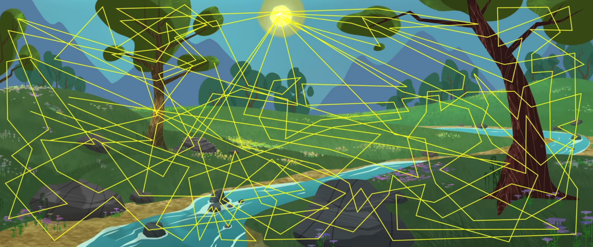
A naive approach
“But we can’t calculate an infinite number of rays!”, one might say, and that is correct! What we can do is to limit the number of rays but this leads to a dilemma: either we have enough rays to make our light realistic but takes a very long time to render, or a sufficiently fast render but incredibly unrealistic results. Furthermore, it is not likely that most of the rays emitted from the light source are going to reach our “eyes”, which means most of the number-crunching work would not be entirely useful to us.
One simple solution, ray tracing
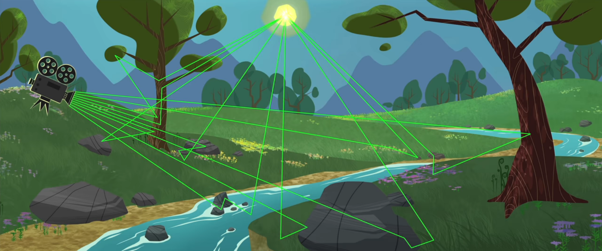
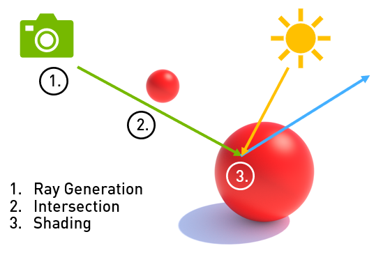
A way to minimise the number of non-useful computations is to look at the problem backwards, or only taking into account the ones that we need: instead of starting our simulation from the light source, we start from our virtual eyes: the camera. A digital image is segmented into individual pixels and for each pixel, we cast out a ray to find what would appear on that pixel by finding the closest object with which the ray intersects. We now know the objects that would be appearing on the screen and their colors. To find out if our point of interest is in direct illumination or in shade, we use secondary rays that work in the same manner. This technique is called “ray tracing” because we are tracing rays around the scene. When we add secondary rays, we are tracing a “path” of rays and this extension is called, unsurprisingly, “path tracing”.
A rather simple, yet powerful, mathematical intuition
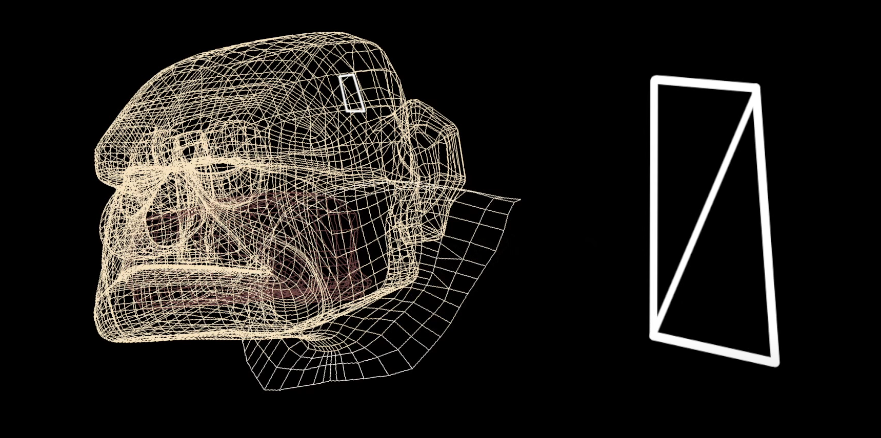
Polygons
Now that we have gotten the gist of ray tracing, let’s find out how we can tell the computer to solve our problem. Every 3D object is made of quadrilaterals called polygons and each polygon can be triangulated into 2 triangles:
Modelling our problem
Finding out whether a ray is intersecting an object essentially means checking if the ray has intersected one of these triangles. Now let’s model our system into a math problem. First, we pick a position for our camera in a coordinate system and call that point . We then create a hypothetical image plane that represents a grid of the pixels that would eventually appear on the viewer’s screen. We pick a pixel on our grid and cast a ray from through which intersects which a polygon at the point .
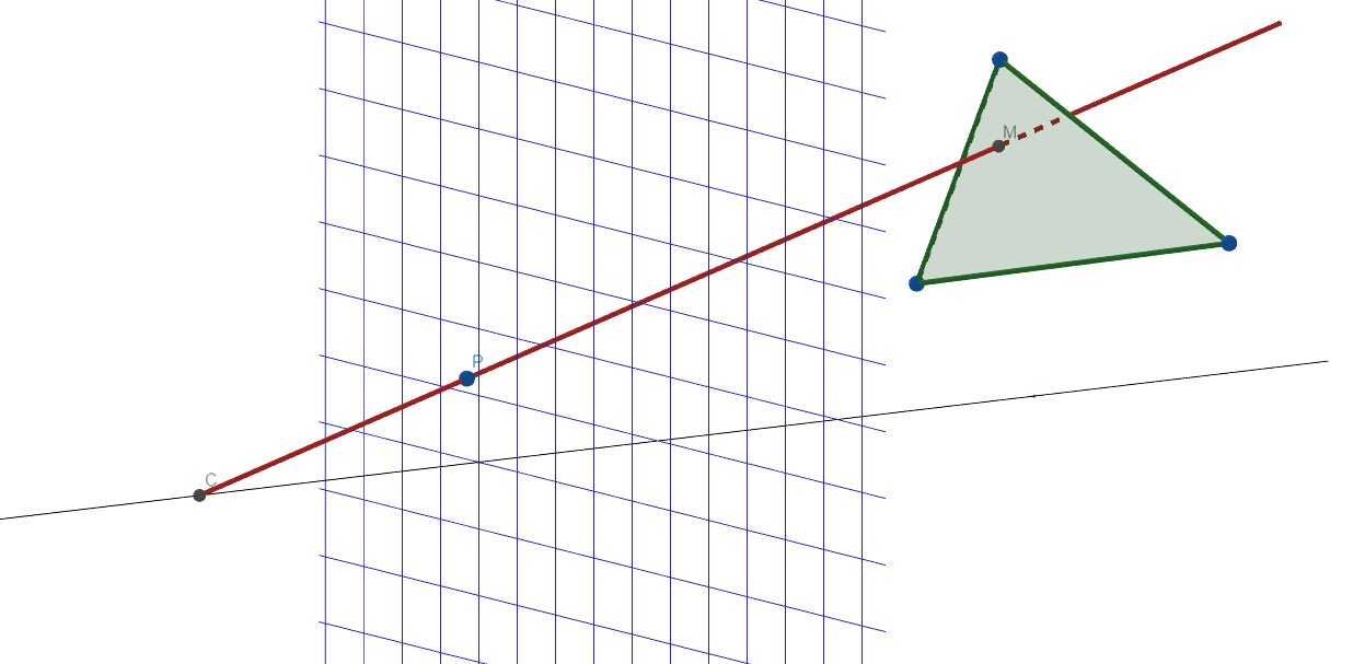 We can then represent our ray () using the 3-dimensional parametric form of the equation for the line going through and with the parameter :
Which represents the following linear system:
Using this form we can easily write as and as . For our polygon, we can write the implicit form of the plane equation going through our polygon:
Finding M
The point lies on the plane, we have:
We know also lies on the ray, this corresponds to a value for , which returns our values for the coordinates of :
We now have a linear system of 4 unknowns with 4 equations:
We substitute our ray equations for into the plane equation for to achieve an equation with a single unknown :
A computer can solve this equation almost instantaneously for the value of , afterward we can substitute into our first system to get the coordinates of . We now have our point:
.
Checking for intersection
The next part of our problem is to examine if lies within or outside our polygon. This does not require any more complicated mathematical tools than what we have been using, in fact it is simply an application of weighted averages. Let us imagine our polygon as the triangle .
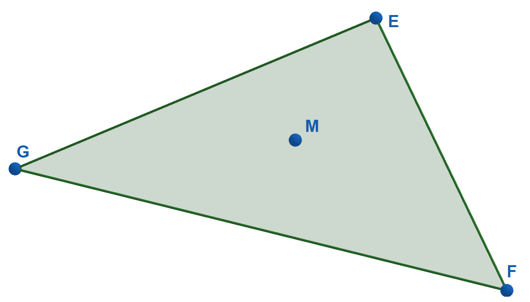
The point can be written as a weighted average of , and as so:
We can understand this as the larger the weight is for a vertex, the further away is from that vertex relative to the other vertices, e.g., if then M is the same distance away from all three vertices ( is the center (or centroid) of the triangle ). If one of the weights is negative, however, then is outside the triangle which corresponds to the fact that our ray does not intersect this polygon.
Currently, our equation seems quite messy being a fraction of variables but there is one key fact that we can use to our advantage: as the weights represent the proportional distance between the vertices, we can scale the weights uniformly and it would not change the position of thus we can limit the weights such that and therefore we can remove the denominator from our equation giving us:
We can solve for the weights using the system of equations with 3 unknowns and 3 equations (again, this task only requires elementary row operations so the computer can solve it swiftly):
We now got our weights and if none of the weights is negative, we have found that our ray intersects a polygon!
Putting it all together
Although we have only managed to figure out what color of the object that would appear on the screen at a pixel is, for realistic lighting we would also want to know if it is in shade. To do this instead of only sending out a single ray from a pixel, we send out a path of rays with each new rays originating from the intersection of the previous. We can use the same math we have used above only now instead of our point , we choose the origin of our next ray to be and the direction of the ray would be determined by the surface of the object (this information is included in the object’s shaders.)
We have found a path tracing process for one pixel, all we need to do is to repeat this process for every other pixels of our image and luckily computers are quite keen of repetitive number crunching tasks like this (modern graphics processors can even do billions at the same time!).
For a large scale production such as a Pixar’s animation, it is standard to use millions of rays for a single pixel and a few dozens or even hundreds bounces for each rays in order to achieve near-realistic lighting. For a marvel that is Toy Story 4, it took 60 to 160 hours to render one frame (this would be impossible if we use the aforementioned naive method) and the movie itself contains a few hundred thousands frames. This resulted in lighting and optical effects that is almost indifferentiable from real camera works.

That’s simply how it all began!
When most people think of advanced technologies they usually think of complex high-level mathematics but in fact, a lot of beautiful and complex creations, both natural or man-made, can be broken down into simple and elegant mathematics that everyone had already learned in school. Throughout this essay, we have discovered that beneath all the layers of abstraction of computer-generated graphics lies a set of simple highschool algebra homeworks.
References
P. Rademacher, “Ray Tracing: Graphics for the Masses”, University of North Carolina, n.d. [Online]. Available: https://www.cs.unc.edu/~rademach/xroads-RT/RTarticle.html. [Accessed May. 14, 2020].
S. Marschner, “Ray tracing”, lecture notes for CS 465 Computer Graphics I, Cornell University, Oct.10, 2003. [Online]. Available: http://www.cs.cornell.edu/courses/cs465/2003fa/lectures/notes-09raytracing.pdf. [Accessed May. 14, 2020].
K. Power. “Ray Tracing”, Institute of Technology, Carlow, Apr. 4, 2008. [Online]. Available: http://glasnost.itcarlow.ie/~powerk/GeneralGraphicsNotes/raytracing.html. [Accessed May. 15, 2020].
GeoGebra 3D, GeoGebra, 2020. [Online]. Available: https://www.geogebra.org/3d. [Accessed May. 14, 2020].
K. Morley, “NVIDIA OptiX Ray Tracing Powered by RTX”, NVIDIA Developer, Apr. 2, 2018. [Online]. Available: https://devblogs.nvidia.com/nvidia-optix-ray-tracing-powered-rtx/. [Accessed May. 15, 2020].
K. Desiderio and I.Phillips, “How Pixar’s animation has evolved over 24 years, from ‘Toy Story’ to ‘Toy Story 4’”, Insider, Jun. 21, 2019. [Online]. Available: https://www.insider.com/pixars-animation-evolved-toy-story-2019-6. [Accessed May. 16, 2020].
Walt Disney Animation Studios, “Disney’s Practical Guide to Path Tracing”, Aug. 9, 2016. [Video]. Available: https://www.youtube.com/watch?v=frLwRLS_ZR0. [Accessed May. 15, 2020].
S. Fong, “Rendering 101”, Khan Academy, Available: https://www.khanacademy.org/partner-content/pixar. [Accessed May. 15, 2020].