
2D Gaussian Shader in Unity
During the very early stages of my thesis project, I was working on having the individual particles data visualised in Unity with IATK. Having the points show up is trivial, but having them rendered in a way that is visually meaningful is a bit more complicated. Eventually, I would have the particles being rendered as a continuos surface with the proper SPH kernel but just to get started, my supervisor suggested we implement a simple Gaussian alpha shader to each particle using its own smoothing length .
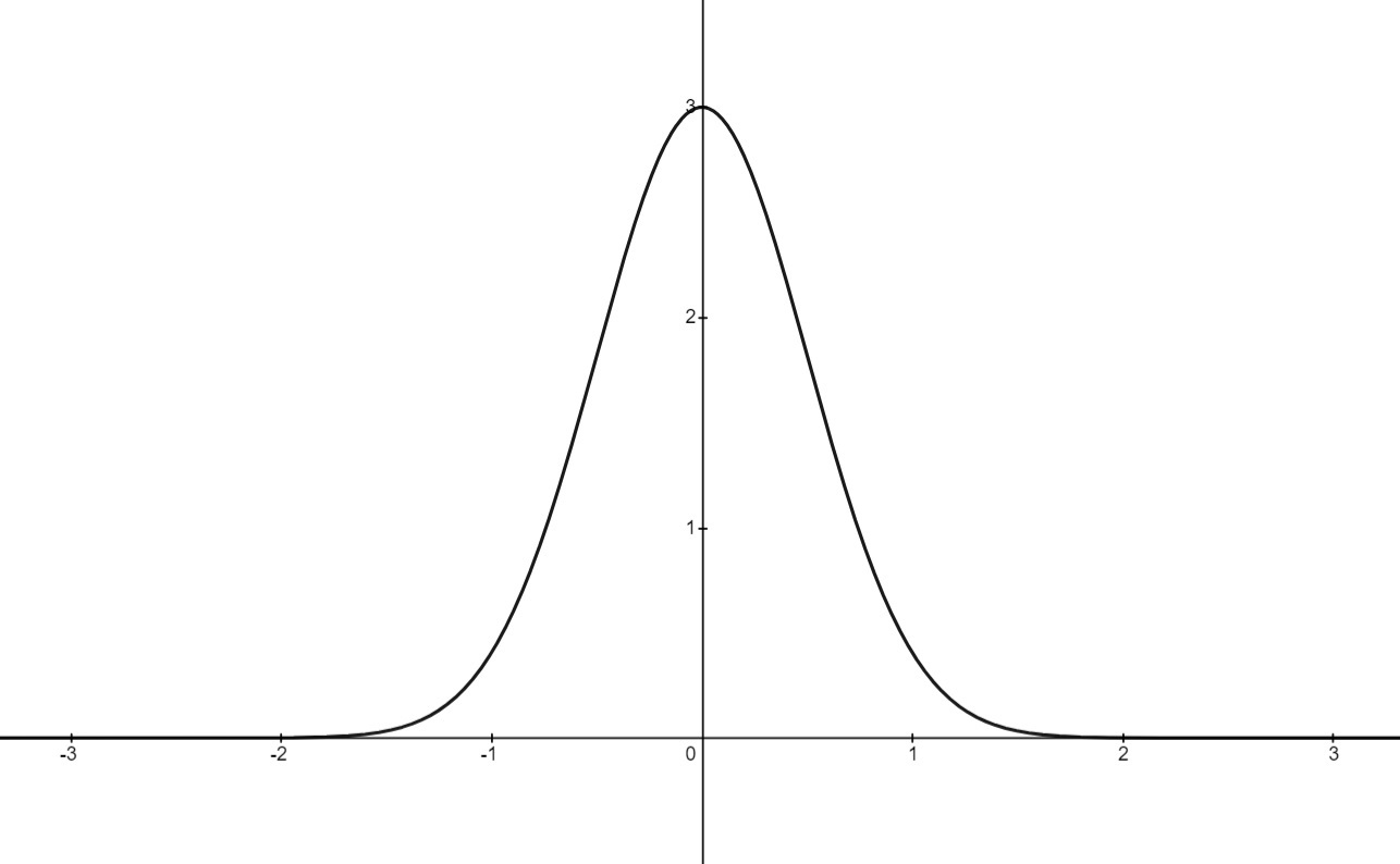
In this post, I will be discussing how I implemented the following Gaussian function to determine the alpha channel of a surface in Unity:
What is a ‘Gaussian’?
It can be confusing at first when you hear people referring to the term a Gaussian but essentially, it is simply a function whose plot is bell-shaped (or more correctly, spreading its parameters in a bell-shaped distribution). Usually I like to think of a Gaussian as some variation of the form:
For the above representation of the Gaussian, is thought of as the height of the peak for our bell curve, will determine the center of our bell curve (how the peak’s position it will be translated from the origin) and will give us how wide the bell curve will be.
 Those who are more familiar with statistics or data science are more likely to recognise it as the probability density function for a Normal distribution:
As the problem I will be tackling doesn’t concern complicated parameters, I will be using a simplified form of one commonly used in mathematics:
Where the function is the value for the alpha channel of our surface shader, which will be in the range and therefore our peak height is . The center of the distribution is determined by our offset parameter and the width of the bell curve is the smoothing length .
Introduction to Unity shaders
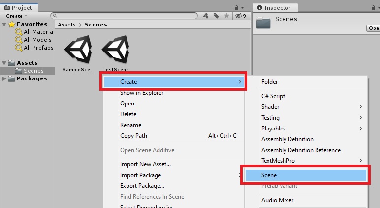
Shaders in Unity is stored in .shader files, which are written in a declarative language called ShaderLab1. Let’s start by creating a new Unity scene by right clicking on the Project window and select Create > Scene, I will have mine named TestScene.
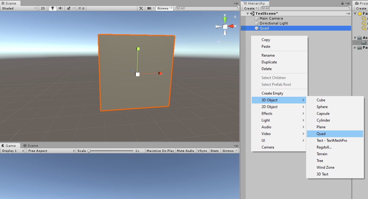
 Next, let’s create some geometry to put our shader on. I will choose a
 Quad, as it is what my particles will be rendered as (a 2-D circle stencil on a square polygon).
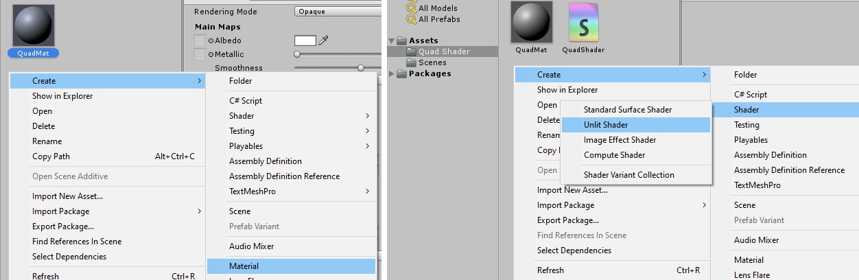
 Now we need to create our Material and Shader files with
 Create > Material and Create > Shader > Unlit Shader (I’m using an unlit shader because my particles will not be affected by lighting).
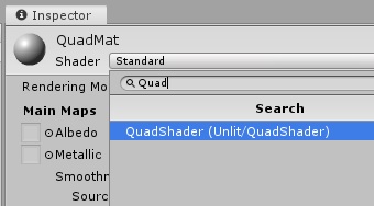
 To use the Material we’ve just made on the geometry, simply drag and drop the Material file from the Project window onto the object in the Scene view. Then we still need to apply our shader to the material we’ve just created, do this by clicking on the Material file in the Project window, in the Inspector, click on the Shader drop down and type in the name of the shader you’ve just created.
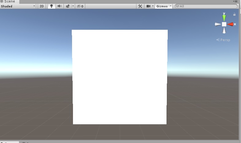
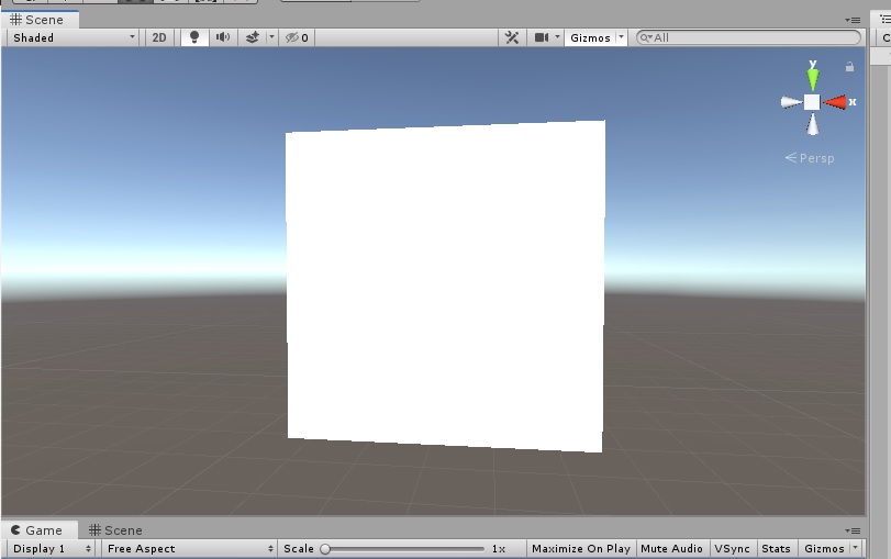
 Now, the appearance of the geometry will have changed based on the type of shader script you’ve just created. For unlit shader, it will be a plain pure white surface. Let’s open the shader script by double-clicking on in the Project window. The script should have already filled in with a templated provided by Unity with the necessary components and structures. To understand what each of the sections do, please check out the documentation from Unity2.
The first piece of code we will be changing is the
Now, the appearance of the geometry will have changed based on the type of shader script you’ve just created. For unlit shader, it will be a plain pure white surface. Let’s open the shader script by double-clicking on in the Project window. The script should have already filled in with a templated provided by Unity with the necessary components and structures. To understand what each of the sections do, please check out the documentation from Unity2.
The first piece of code we will be changing is the Properties. This part contains names and declarations of variables that we will be passing to the GPU from the Inspector, so convenient! I will be adding my and values as it will be used by the surface shader to calculate the alpha value. I will add a tint to set the surface color of the geometry as well.
# Before:
Properties
{
_MainTex ("Texture", 2D) = "white" {}
}
# After:
Properties
{
_MainTex ("Texture", 2D) = "white" {}
_MainTint ("Main Tint", Color) = (1,1,1,1) # Base color of the surface
h ("h - smoothing length", Range(0,1)) = 0.5 # Smoothing length h from 0 to 1
b ("b - center offset", Float) = 0.5 # Center of the Gaussian
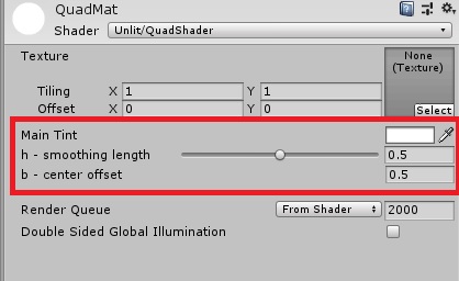
}Note that is is good practice to keep the same naming conventions for these variables (_CapitalCamelCase) while writing your code, I’m keeping mine as h and b for the sake of testing (please don’t do it)! Let’s go back to the editor and see what have changed. We can see that our newly added variables can be changed conveniently in the Inspector itself. The variable type3 also reflects how the selection is presented in the Inspector GUI (i.e. Range will have a slider and Color will have a color selector).
Working with the GPU
What we have just done is we have informed Unity of what to provide to the GPU for calculation, but the GPU still has no idea of what those variables are or if they even exist, thus we have to declare them properly in SubShader’s Pass section of the code as well, as this is what will be executed by the GPU. Right before the vert function (v2f vert (appdata v)) line, we can declare our variables here together with the existing _MainTex variable. The names must match what you have put in the Properties as Unity will be matching the names’ strings value to deliver their corresponding data.
# Before:
SubShader
    {
        ...
        ...
        Pass
            {
                ...
                ...
                sampler2D _MainTex;
                float4 _MainTex_ST;

                v2f vert (appdata v)
                ...
                ...

# After:
SubShader
    {
        ...
        ...
        Pass
            {
                ...
                ...
                sampler2D _MainTex;
                float4 _MainTex_ST;
                fixed4 _MainTint;
                float h;
                fixed b;

                v2f vert (appdata v)
                ...
                ...
The types4 of these variables might be unfamiliar to you but basically, float4 is a vector (or you can imagine it as an array) of 4 float values, so as fixed4 - which is a vector of 4 fixed values (Lowest precision fixed point value. Generally 11 bits, with a range of –2.0 to +2.0 and 1/256th precision). Notice that our Color variable is a fixed4, this is because Color is essentially a vector representing 4 channels of RGBA with each channel having a value clamped to the range .
Time to implement the math
Now, with the data ready to be used, we can finally do some math! For the purpose of this guide, we will be sticking with the Fragment shader and skip the Vertex shader. In short, the Fragment shader is the last stage (not really, but for now it can be intepreted as such) of the rendering pipeline, which determines how the pixels will be displayed on your screen. The Fragment shader code is used to interpolate between the vertices of your polygon and decide how they will appear on the screen, while the Vertex shader can alter the vertices, changing the how you see the geometry of the polygon (but not the actual polygon itself). Our target function here is the fixed4 frag (v2f i) : SV_Target function near the end of the file. Currently it is not very exciting:
fixed4 frag (v2f i) : SV_Target
    {
        // sample the texture
        fixed4 col = tex2D(_MainTex, i.uv);
        // apply fog
        UNITY_APPLY_FOG(i.fogCoord, col); # We can remove this as we're not using fog.
        return col;
    }
Let’s try to see what it is doing. First it looks like it is creating a vector of 4 fixed values and returning it. That’s actually the color of the pixel that will be displayed on the screen! Meaning right here, right now, you have the full power over what every single pixel of that object will appear on the screen! Now that’s a magical feeling!
 The
The tex2D function seems like it is doing something with the _MainTex which is the base texture that was included with the script template, I’m guessing it is trying to set the pixel’s color to be matching the texture’s color in the corresponding position. But we’re not using a texture so let’s ignore that line and do some investigation! If I change the red channel of the col vector to 1, the quad should now be red:
fixed4 frag (v2f i) : SV_Target
    {
        fixed4 col = tex2D(_MainTex, i.uv);
        col.r = 1;  # You can refer to the channels with 'r','g','b' and 'a'.
        return col;
    }
Hmmmm… That was dumb, of course it is still white, as white means all the channels are already 1! Let’s try again with the green and blue channels set to 0 and with it let’s do some thing to see what the
 i.uv part actually is:
fixed4 frag (v2f i) : SV_Target
{
fixed4 col = tex2D(_MainTex, i.uv);
if (i.uv[0] < 0.5 && i.uv[1] < 0.5) {
col.r = 1;
col.b = 0;
col.g = 0;
}
return col;
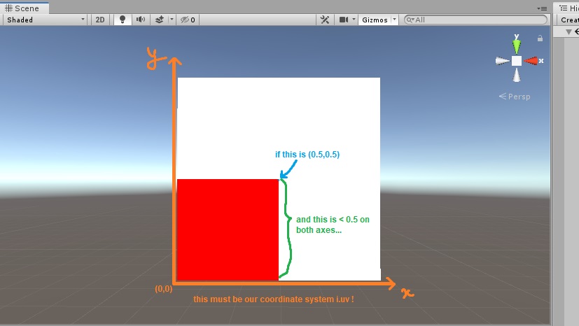
}We have a red square on the bottom left quarted of the quad now! I might have cheated a little bit with some foresight by doing this once before, but now we can see that i.uv seems to be a vector or more specifically a point on the geometry with their values seemingly also clamped from 0 to 1 with the origin being in the bottom left corner.
Okay, now back to the real math. Let’s see what we have to do to get our Gaussian function implemented here. Recall we have the function:
This is only for a 1-dimensional value but we need 2 values for and coordinates. To extend this to 2-dimensions, let’s look at where our calculation is dependent on the parameters. Only in ! This makes it much easier. Now that we are not only shifting on the axis but also on the axis as well, we need to extend this 1-D relation ship between our axis and our offset to 2-D by changing both of the terms to 2-D: becomes a point and becomes a vector . We need to shift both of the dimensions similarly:
As we are shifting both dimensions equally by the amount , we have the final equation:
Seems like we will have to do powers and exponential function in our calculation. Luckily, our script is using Cg - a shader programming language from NVIDIA, which comes packaged with super helpful math functions5 such as pow() and exp()! We can now do the math in our shader code (notice I’ve set b to be 0.5 by default from the Properties section above):
fixed4 frag (v2f i) : SV_Target
    {
        fixed4 col = tex2D(_MainTex, i.uv)*_MainTint; # Applying the base color to our geometry.
        float x = i.uv[0]; # This is our x value
        float y = i.uv[1]; # This is our y value

        float value = exp(-(pow((x - b), 2) + pow((y - b), 2)) / (2 * pow(h, 2)));
        col.a = value; # Setting the alpha channel so it is more transparent the further away from the center.

        return col;
    }
Investigating the shader transparency
That’s very strange, seems like setting the alpha channel value is not doing what we have expected. Let’s try setting the color channels instead to see if our calculation is even working, and we already know setting the color values work.
fixed4 frag (v2f i) : SV_Target
    {
        fixed4 col = tex2D(_MainTex, i.uv)*_MainTint;
        float x = i.uv[0];
        float y = i.uv[1];

        float value = exp(-(pow((x - b), 2) + pow((y - b), 2)) / (2 * pow(h, 2)));
        col.r = value;
        col.g = value;
        col.b = value;

        return col;
    }
So it must not have been our math that was wrong (now that’s something you never hear). After some Googling, it appears we have to declare our ShaderLab Blend mode in order for the GPU to know how to combine the output of our fragment shader6. We do this by adding Blend SrcAlpha OneMinusSrcAlpha before our Pass block:
...
SubShader
{
Tags { "RenderType"="Opaque" }
LOD 100
Blend SrcAlpha OneMinusSrcAlpha
Pass
{
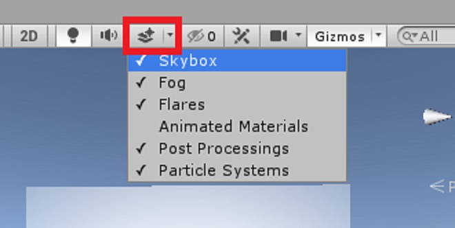
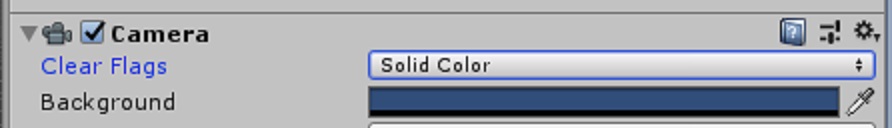
... It appears to be working but we can’t really see what’s going on with the skybox enabled. Disable this by clicking on this button on the top bar of the scene view:
 Now let’s see what we’ve got (The GIFs’ low bitrate compression made the color banding appear super ugly here, but it should be much nicer running on your computer):
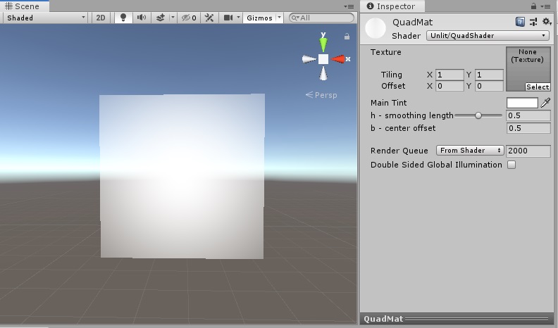
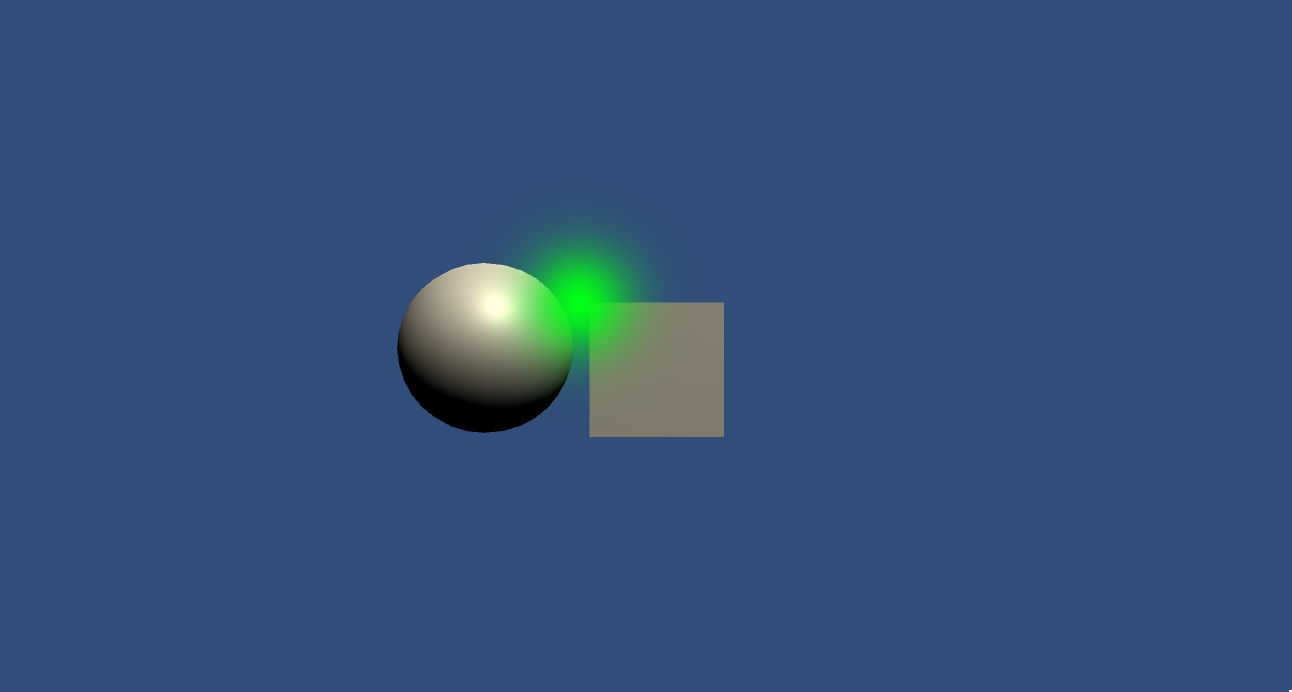
 Below are some uncompressed screenshots of what the transparency should look like:

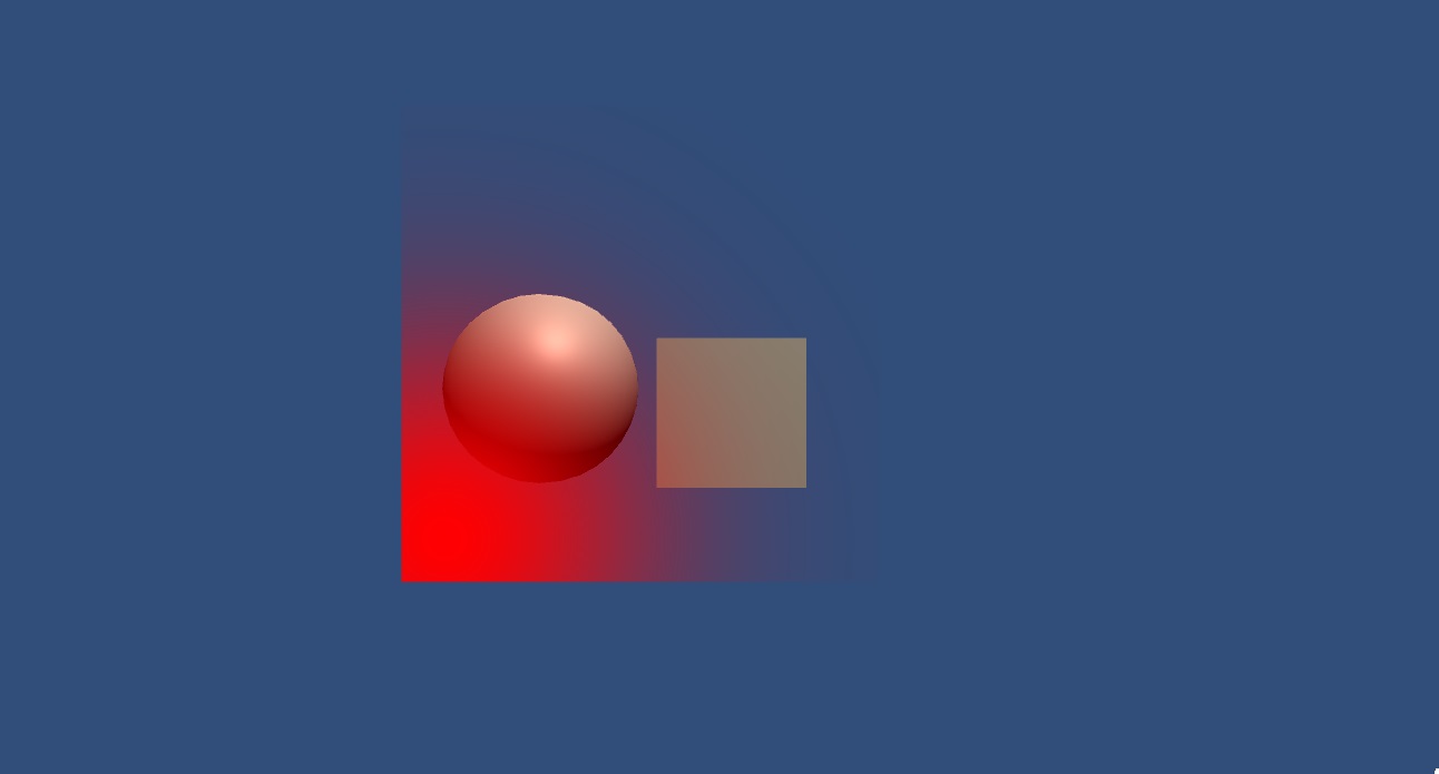
We have a functioning Gaussian shader! Hopefully, with this basic introduction to Unity shaders and your creativity, you can make something much cooler than what I did here. Also, if you have noticed any errors or inefficiencies in what I have written, please let me know! I wrote this article while I was learning how to do it so I still have so much more to improve. (One thing I noticed is that doing the math for every single pixel on the screen is super expensive and as it is not dynamic, I think it should be precalculated and have the values of the Gaussian stored as a banded array).
References
Footnotes
-
Unity’s documentation on Custom shader fundamentals. ↩
-
Unity’s documentation on ShaderLab: defining material properties ↩
-
Unity’s documentation on Shader data types and precision ↩
-
See Table E-1 on NVIDIA’s Developer Zone: The Cg Tutorial - Appendix E ↩
-
Unity’s documentation on ShaderLab command: Blend ↩